June 26, 2021
Like with resistors, it is tempting to verify the functionality of Apex power op-amps with an ohmmeter. Meter readings between pins of the suspect device are compared with readings between the same pins of a known good device. If the readings do not match, the suspect op-amp apparently is dead. Although this method sometimes seems to work, it’s too simple to tell the whole story behind a complex device such as a power op-amp, which is a multi-pin, active component. Moreover, when using this method, a device may test good, when it is not.
Therefore, it is much better to test the suspect op-amp in-circuit. Sometimes it is possible to isolate the op-amp with its peripheral components in an existing circuit, otherwise a simple test circuit needs to be built - the simpler, the better. Apex Evaluation Kits (EKs), especially when equipped with pin sockets for the Device Under Test (DUT), provide a perfect platform for in-circuit testing.
If possible, go for an inverting configuration. Check the datasheet for the gain at which the op-amp has no stability concerns, as some Apex devices are not unity-gain stable, like PA50 and PA52 (stable at gain ≥ 3), or PA107DP (stable at gain ≥ 20). Pick an ‘easy’ gain, realizing that lowering the gain has inadvertent effects on stability. Also check for the value of an any necessary external phase compensation capacitor. The datasheet contains either a table or a graph to select a value for various gain values/settings. Note that the phase compensation capacitor must be rated for the full supply voltage.
Although the described electrical test should be performed at the minimum supply voltages while the amplifier is unloaded, quiescent power dissipation can be considerable. As an example, the quiescent current IQ of PA94 is specified as 24mA max, and its minimum supply voltages as ±50V, for a quiescent power dissipation of 100 * 0.024 = 2.4W. This would already require the mounting of PA94 on a heatsink.
A number of Apex op-amps feature a current limit function. The current limit can be set by means of a current sense resistor and if exceeded, the output voltage will be driven such that the current cannot increase. For this simple in-circuit test, the sense resistor’s value can be 0 Ω, understanding that the current limit feature is disabled and not tested.
Some Apex op-amps have inputs to disable the device’s output stage. As that’s one of the key sections of the op-amp to be tested, care should be taken that these inputs have the right potential for the output to be enabled. This often means that the associated pin can be left floating, but it is a good idea to confirm this using the product’s datasheet.
The datasheet of each Apex power op-amp delineates a minimum value for the power supply voltages. Use this value for the in-circuit electrical test. Some Apex power op-amps feature a boost function that allows for a higher output voltage swing at the same ±VS supply voltages, but for the purpose of this electrical functionality test, connect the extra ±VB pins to the ±VS pins. Always use the main power switch of the power supplies to turn the op-amp’s supply voltages on and off. Do not use relay contacts or manual (un)plugging of banana plugs. Once the power is on, and if available, check the current meter reading on the power supply to match the value for IQ in the datasheet.
Turn the power supply off and prepare a sinusoidal input signal with a frequency of 1 kHz and an amplitude such that the output of the amplifier can make a full swing, keeping amplifier gain, supply voltages, and eventual supply to output voltage drops in mind.
Connect the input signal to the circuit, but don’t turn it on yet. Power up the amplifier circuit and turn on the input signal. With an oscilloscope, check the circuit’s output signal; it should be sinusoidal, either inverted or non-inverted, have a frequency of 1 kHz, and an amplitude equal to the gain times the input signal’s amplitude.
If this is indeed the case, the amplifier is functional at a base level and you are ready to do more tests, like increasing the frequency or applying a load. If the output signal is not as expected, check your circuit; if it is correct, there is a big likelihood the amplifier is dead.
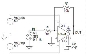
Figure: Example test circuit based on PA94 (left) and associated oscilloscope graph for a GOOD DUT (right).
|
|
Power Operational Amplifier products
Back