June 1, 2021
Q
Is there a limit to how many amplifiers I can parallel?
A
When designing an op-amp circuit the designer is faced with several critical considerations; one among those is desired output current. In an ideal world the designer selects an op-amp that can satisfy all desired circuit conditions to minimize the number of components in the circuit . Unfortunately, the real-world case is often that performance tradeoffs must be made when an op-amp is well suited for one aspect of a design but falls short of meeting others.
For example, a challenging application might require a high slew rate of 900V/µs and a high continuous output current of 5A. After some investigation the designer may find that there is an op-amp available that can provide the 900V/µs but can only provide 5A peak output current. Because high current high speed op-amps, like Apex’s PA119, are not common, the designer must identify an alternative solution to increase the output current of the 900V/µs op-amp to enable its use in the target application. One available solution to this problem is a parallel design.
In applications where an available op-amp satisfies one or more key qualifying characteristic(s) that make it desirable, but the circuit conditions require more current or power than the op-amp is rated for, the op-amp can be paralleled with another op-amp to share the output current across multiple devices. When evaluating the use of parallel amplifiers, one must consider the benefits and tradeoffs associated with this technique; parallel topologies provide increased output current capability while reducing stress on the individual op-amps, improving the ability to operate within the SOA at the cost of reduced stability, diminished bandwidth, and increased BOM part count.
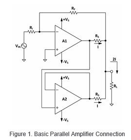
Figure 1 depicts a parallel system consisting of two op-amps. The input signal is being sourced into the inverting input of A1 with gain setting resistors calculated as RF/RI. A2 is configured as a unity gain follower with the input signal being fed to the non-inverting input of A2 from the output of A1. If the application requires a signal frequency exceeding half the power bandwidth of the amplifier, it may be an unsuitable choice. RS is used as a current sharing resistor intended to balance the current sharing of the two amplifiers, compensating for small errors whether it be varied offset, slew rate, etc. In conjunction with current limiting, this configuration can be used to preserve either amplifier in the event that an amplifier in the system fails. It should be noted that the parallel configuration is not limited to a single follower amplifier, and that multiple unity gain followers can be added. However, increasing the number of followers also increases difficulties in maintaining good signal fidelity as well as equal current sharing throughout the system.
As the number of amplifiers in a parallel system grows, limitations will be reached. For example, as the tuning of RS and compensation capacitors increases in complexity it can become detrimental to output signal fidelity and/or stability. Further adjustments made to maintain fidelity and stability can cause losses in bandwidth, which may negate the benefits of the original amplifier selection. Additionally, as the quantity of paralleled amplifiers increases, so too do the impacts of layout. With increases in the physical size of the circuit, poor layout practices will become more apparent; whether it be ground loops, poor isolation, etc.
One of the most important things to consider when selecting amplifiers for a parallel application is that they must have closely matched characteristics, and if possible, should be the same model op-amp with the same part number. This helps ensure that the output current is shared equally between all amplifiers in the system. Additionally, employing techniques to compensate for instability is often advantageous in terms of maintaining signal fidelity. This can be accomplished by increasing an op-amps compensation capacitance or by increasing the value of the current sharing resistor, RS. Mismatching characteristics can cause individual op-amps in the system to be overstressed inducing instability into the circuit.
For further information, please reference AN26 in the Apex Application Notes Library!