August 1, 2020
Let us look at how to calculate this noise gain through the example of a PA89 amplifier with a gain of 50.
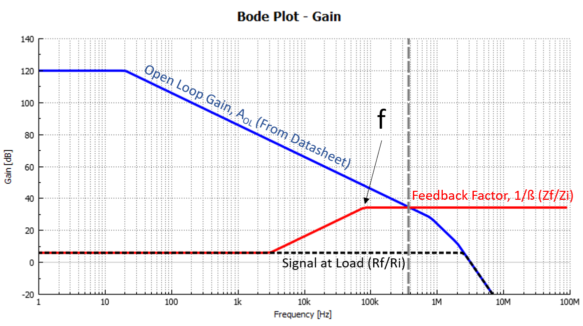
Consider the following image in the PA89's datasheet:
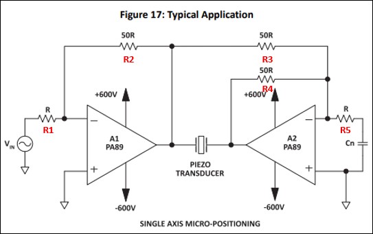
Rn (=R5) and Cn raise the apparent gain of A2 (follower amplifier), so that both amplifiers can be used with the same phase compensation components and have the same phase response. Although PA89's datasheet calls out to make Rn = R5 = R for an (apparent) gain of R4/R5 = 50R/R = 50, we normally recommend to choose Rn ≥ 0.1*R3 for an apparent gain shift of ≤10 (20dB) only. This would require choosing the gain of the primary amplifier (now: R2/R1 = 50R/R = 50) ≤10, too.
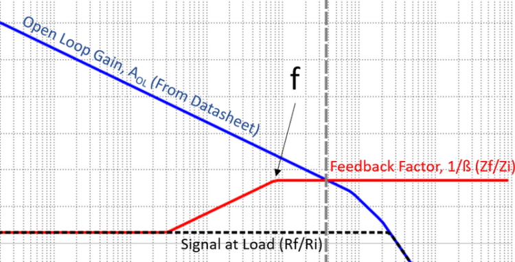
But following the datasheet: Rn = R5 = R, Cn becomes 1/(2*π*f*Rn), with f being the pole in this picture:
To get a better idea of how to choose Cn, and of stability of your circuit in general, please use Apex free Power Design Software Tool.
If you download this file and import it into Power Design, you will see the pole can be set at ~80kHz with Cn = 2nF. Of course, a lot depends on your load. A 2nF load had arbitrarily been chosen, which would be half the capacitive load each amplifier in the bridge 'sees' (2nF+2nF = 1nF, would be the actual load between the outputs of the bridge).
Recall April's newsletter for a good tutorial on Noise Gain.
Back