October 8, 2026
A digital audio system can achieve total harmonic distortion and pass sound testing with flying colors but still have underlying factors that affect the true clarity. The specs check out, distortion sits well below audible thresholds, noise performance looks clean on paper. Yet there are still more variables that affect the quality of the signal, sitting just below the threshold of audibility.
A clock signal is often treated as a supporting element within a digital audio system, but its precision can have a direct impact on overall performance. Even when converters, amplifiers and other signal-chain components perform as expected, clock precision can become a limiting factor. The clock serves as the heartbeat of a digital audio system, making its accuracy, precision and stability important design considerations.
This is where jitter and phase noise enter the conversation. Jitter describes timing errors in a clock signal, while phase noise characterizes those errors in the frequency domain. Together, they provide insight into how accurately a system samples, converts and reconstructs audio. They illustrate a broader challenge in audio evaluation: some performance issues become apparent only when measurements move beyond traditional headline specifications.
Why Timing Errors Matter
In the frequency domain, those timing variations appear as phase noise, giving engineers another way to evaluate clock precision and stability.
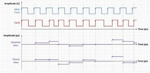
Figure 1 shows how those timing deviations appear as shifts in clock-edge position and cycle duration.

Figure 1. Time Domain Representation of Absolute and Period Jitter
In audio converters, those timing deviations couple into the sampling process and modulate the input signal phase. The result is new distortion products and changes to the signal’s spectral behavior. As shown in Figure 2, timing errors in the clock domain can translate into phase modulation and spectral artifacts at the converter output.

Figure 2. Time and Frequency Domain Representation of Clocks and ADC Input and Output Signals
Depending on the nature of the clock behavior, those effects can appear as signal spread, elevated noise floors or tonal artifacts in the frequency domain. That distinction matters because these artifacts are not always captured by conventional performance metrics alone.
What Traditional Measurements Miss
Performance in a digital audio system can degrade even when Dynamic Range (DNR) and Total Harmonic Distortion Plus Noise (THD+N) measurements remain largely unchanged. This doesn’t make the measurements unimportant but does mean that they don’t always capture every behavior that affects system performance. It becomes especially clear when evaluating jitter and phase noise.
Random jitter tends to raise the noise floor. Deterministic jitter can create discrete distortion spikes tied to the signal and jitter frequency. Low-frequency phase noise can spread energy around a signal tone even when conventional THD+N and DNR measurements show minimal degradation. Figure 3 demonstrates how low-frequency phase noise spreads energy around the fundamental tone despite relatively stable conventional measurements.

Standard FFT (Fast Fourier Transform) views also have limitations. They provide a useful snapshot of system behavior, but they may lack the resolution needed to uncover faint tonal structures or low-level modulation artifacts. With higher-resolution FFT analysis and sufficient averaging, small spectral features begin to emerge, including distortion components, raised noise floors and with skirt-shaped spreading around signal tones.
Figure 3. ADC Performance vs Frequency with Clock 4

Figure 4. Magnified View of Phase Modulation (shown in Figure 8)
Figure 4 provides a magnified view of that tonal spread, revealing modulation artifacts that conventional measurements can understate. In some cases, those artifacts could easily be missed without deeper spectral analysis.
This is where jitter and phase noise become more than clock specifications. They become a case study in why audio evaluation increasingly requires measurements that look beyond aggregate numbers.
Time, Transients and Perception
That disconnect between headline specifications and spectral behavior highlights a broader issue in audio evaluation. Two systems can produce similar measurement results while behaving different under operating conditions. For engineers designing digital audio systems, those differences have practical consequences. Decisions around converter architecture, clocking, filtering and noise behavior influence how reliably detail carries through production and playback.
Jitter is only one example. Engineers can also use methods such as 1 Hz testing and high-resolution spectral analysis to uncover low-level modulation effects, noise-floor behavior and tonal artifacts that can remain hidden from traditional measurements. This is the role of euphonic testing, where designers connect objective analysis directly to how systems behave in listening environments. Instead of asking whether a device meets a specification, the question shifts to whether its behavior aligns with what the ear detects.
Where Measurement Meets Listening
Metrics such as THD, dynamic range and DNR remain important but don’t tell the complete story. Measuring further provides the context that these numbers lack.
As audio workflows continue to evolve, the standard for evaluation is shifting alongside them. Jitter and phase noise show why that shift matters and demonstrate that accuracy is not just a number. It is the point where measurement and system behavior arrive at the same conclusion.