November 3, 2020
MEMS microphones are typically constructed by placing two semiconductor chips into a single package. The first semiconductor chip is a MEMS membrane which converts sound waves into an electrical signal, while the second chip is an amplifier that sometimes contains an analog-to-digital converter (ADC). An analog output signal is made available to the user if the ADC is not included in the MEMS microphone and a digital output signal is present if the ADC is included.
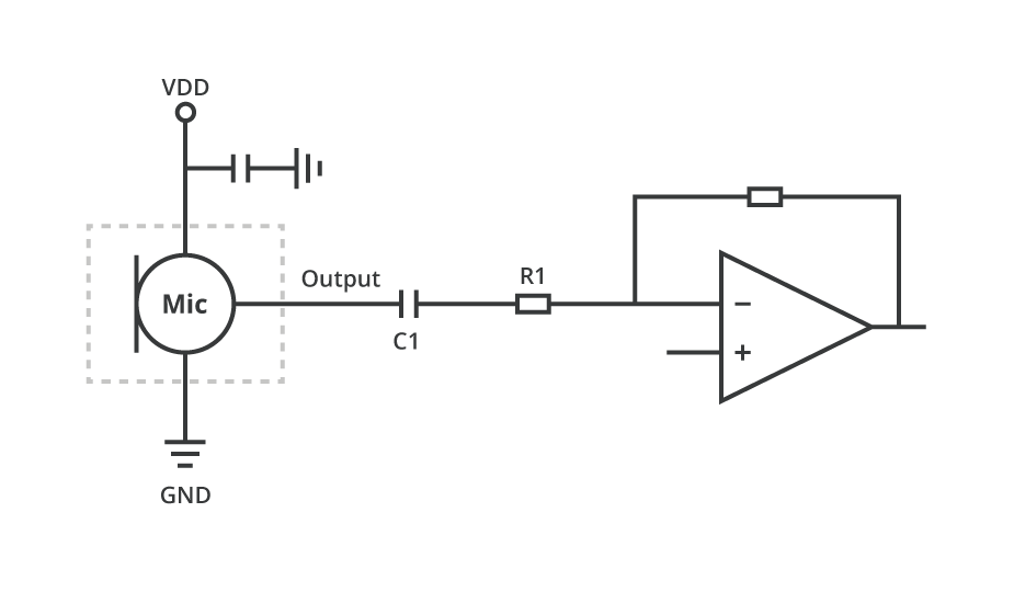
MEMS microphones with analog outputs allow for a straightforward interface to the host circuit, as shown in the figure below. It should be noted that the analog output signal of the microphone is driven by an amplifier internal to the microphone. Therefore, it is already at a reasonable signal level with a fairly low output impedance.
The dc blocking capacitor (C1) is employed so the dc input voltage of the host circuit does not need to be matched to the dc output voltage of the MEMS microphone. The pole frequency created by the combination of C1 and R1 needs to be set low enough such that the desired audio frequency signals are passed to the host circuit with an acceptable level of attenuation [i.e. for minimum audio frequency range of 20 Hz; 1/(2*π*R1*C1) < 20 Hz].
The output signals from MEMS microphones with a digital interface are often encoded with pulse density modulation (PDM) or I²S. With PDM the analog signal voltage is converted into a single bit digital stream containing a corresponding density of logic-high signals. Some of the advantages of PDM include electrical noise immunity, bit error tolerance, and a simple hardware interface.
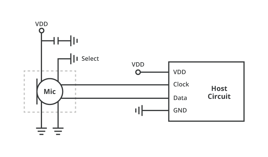
The figure below shows how a single digital microphone with PDM output can be connected to a host circuit. Connecting the "Select" pin to either Vdd or Gnd in the figure will determine if the data is asserted on the rising or falling edge of the clock signal.
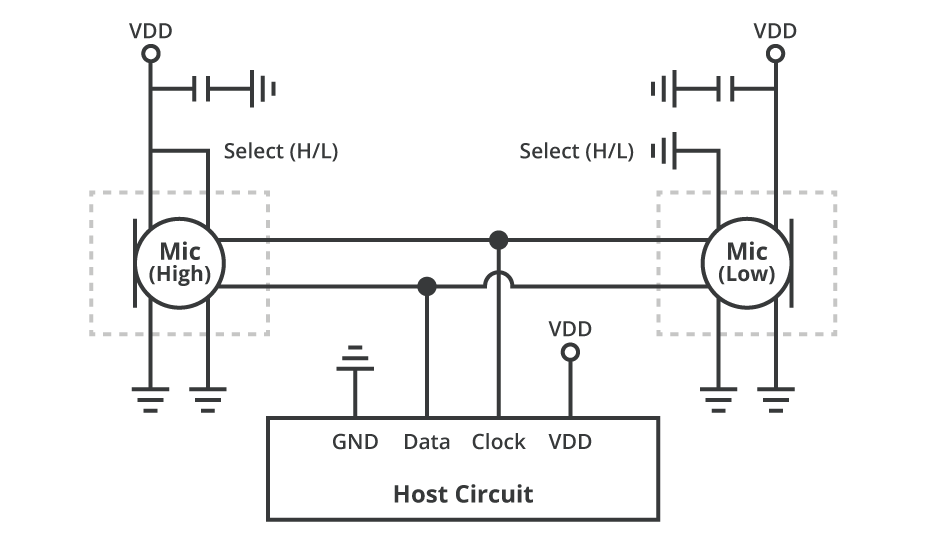
The diagram below shows how two microphones can be connected to the host circuit using shared clock and data lines. This configuration is often employed when implementing stereo microphones.
Offering similar system benefits as PDM outputs, I²S output MEMS microphones contain an internal decimation filter that allows the microphone to produce a standard audio sample rate for simplified interfacing and processing. Because this decimation occurs internally, digital I²S MEMS microphones can connect directly to a digital signal processor (DSP) or other controller, eliminating the need for an ADC or codec to process the outputted data. This can lower system design costs and lead to space savings in the final application. As with digital PDM MEMS microphones shown in the figure above, two digital I²S MEMS microphones can also be connected using a common data line, but they require two clock signals instead of one as well as a word clock and bit clock.
The decision to employ MEMS microphones with analog or digital output signals is often dependent upon how the output signal will be used. An analog output signal is convenient if it will be connected to the input of an amplifier for analog processing within the host system. Examples of conventional analog applications are a simple loudspeaker or radio communication system. MEMS microphones with analog outputs also tend to have lower power consumption than those with digital outputs due to the absence of the ADC.
A digital output signal from a MEMS microphone is advantageous when the signal will be applied to digital circuitry, typically a microcontroller or digital signal processor (DSP). The digital output signal can also be beneficial if the conductors between the microphone and the host circuit are in an electrically noisy environment because the digital output signals will exhibit greater electrical noise immunity than would traditional analog signals.
MEMS microphone technology is here to stay, so it is important to understand the various available configurations. When it comes to choosing an analog or digital output, the decision comes down to how the output signal will be used and what type of system it will be implemented in. Thankfully CUI Devices offers a variety of MEMS microphones in analog, digital PDM, or digital I²S outputs to help match the specific requirements of your design.
Back