June 5, 2020
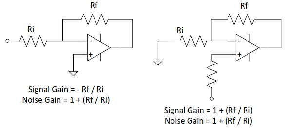
Operational amplifiers are associated with two types of gain - signal gain and noise gain. While signal gain depends on the input configuration of the op-amp (-Rf / Ri for inverting amplifier and 1 + (Rf / Ri) for non-inverting amplifier), the noise gain of an amplifier remains 1 + (Rf / Ri) for any configuration.
The Noise gain of an amplifier is used to understand the stability of an op-amp and is the same gain that is shown in gain vs. frequency response bode plots. Noise gain compensation is a technique where the noise gain of an amplifier is set at a different value from the signal gain in an effort to stabilize the amplifier.
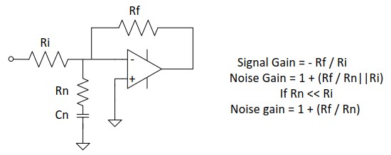
Most high-power amplifiers are inherently unstable at lower gains. This can be a problem when an application requires the use of an amplifier in a bridge configuration or as a unity gain buffer. In such cases, a resistor "Rn" in series with a capacitor "Cn", can be connected between the inverting input and non-inverting input of the amplifier. The signal gain (or DC gain) of the amplifier is set at a desired lower gain by the ratio of Rf and Ri. However, if Rn << Ri, then the noise gain is set by the ratio of Rf / Rn and is high enough such that it ignores the high frequency pole in its open loop gain plot. This causes the amplifier to behave as if it is being operated at a higher gain. However, Vout / Vin remains set by Rf / Ri.
This technique can be used for any amplifier application where stability is required at a gain lower than the specified minimum gain provided in datasheet.
Application note AN19 details various techniques to improve amplifier stability, including noise gain compensation.
Back
